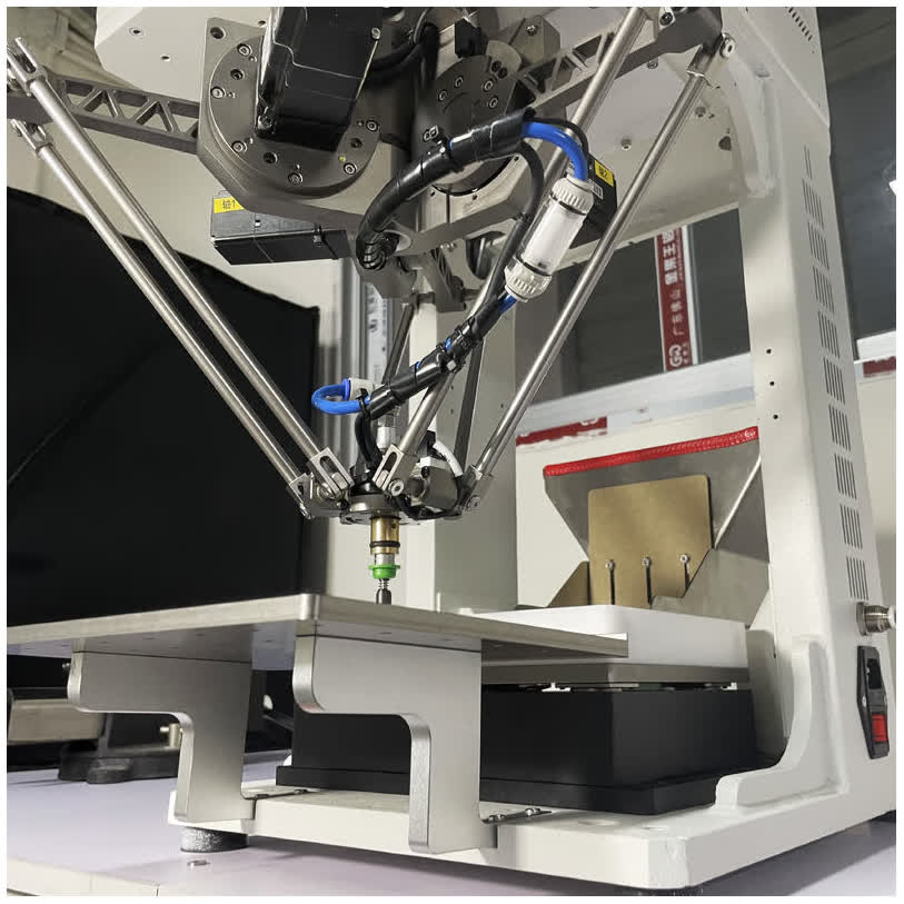

SHENZHEN, GUANGDONG, CHINA, October 30, 2026 /EINPresswire.com/ — Sourcing high-speed automation equipment requires looking beyond headline marketing numbers to evaluate real production capabilities. Deploying a Desktop High Speed Pick and Place Robot increases throughput in electronics assembly, pharmaceutical sorting, and precision packaging lines. However, supplier data sheets often present idealized metrics that mask real-world performance limitations. When evaluating benchtop automation, equipment buyers must scrutinize dynamic repeatability, structural frame mass, speed de-rating curves, and vision integration latencies. A rigorous comparison of six core performance factors ensures that selected equipment delivers sustained throughput and long-term production reliability.
True Operational Throughput vs. Theoretical Cycle Time
The most common pitfall in equipment selection is relying on theoretical unloaded cycle times published on promotional data sheets. Robot manufacturers frequently quote peak speeds based on idealized micro-motion strokes, such as a ten-millimeter vertical hop across a fifty-millimeter horizontal span, measured with zero end-effector payload and without vision inspection delays. While these bench tests produce impressive cycle figures on paper, they rarely reflect real factory conditions.
Buyers must demand validated throughput data under standard operational benchmarks: – Standard transfer spans: A meaningful industrial benchmark evaluates a standard path lifting 25 millimeters, translating horizontally across 300 millimeters, lowering 25 millimeters, and returning. – Auxiliary motion times: Real cycles must incorporate vision image capture, lighting strobes, pneumatic vacuum activation, and settling delays. – Sustained production pacing: High-performance systems reliably maintain net throughput between 3,000 and 4,500 parts per hour across continuous eight-hour shifts, equating to 50 to 75 parts per minute. – Part feed replenishment: Operational throughput depends on upstream feeding stability, where part dispersion and settling times directly affect robotic pick readiness.
Evaluating verified sustained throughput rather than theoretical unloaded speed prevents lines from falling short of required output targets after factory commissioning.
Dynamic Repeatability Under High Acceleration
Positioning precision under static laboratory conditions differs significantly from dynamic repeatability during continuous high-speed cycling. Standard data sheets typically highlight static repeatability measured while the robot moves slowly between stationary points. However, when a Desktop High Speed Pick and Place Robot accelerates at 10g to 15g, massive inertial reaction forces act upon structural linkages, drive belts, and joint bearings.
Evaluating dynamic repeatability requires examining several critical mechanical factors: – Dynamic settling time: The time required for structural oscillations to dampen down before the end-effector releases a component into a precision nest. – True-position tolerance: High-performance parallel Delta robots maintain dynamic repeatability of ±0.05 mm even under peak kinematic accelerations. – Linkage stiffness: Hollow carbon fiber rods and preloaded zero-backlash spherical joints eliminate mechanical play that causes positional drift. – Thermal expansion stability: Sustained high-frequency cycling generates heat inside motor housings, requiring temperature compensation algorithms to maintain coordinate accuracy.
Demanding dynamic repeatability certification ensures that components seat accurately into delicate connectors, PCB pads, or optical fixtures without mechanical misalignment.
Structural Base Mass and Harmonic Vibration Damping
Dynamic accelerations exceeding 10g generate severe reactionary forces that must dissipate through the machine frame. A lightweight aluminum profile frame tends to flex and resonate when high-frequency directional reversals occur, creating mechanical harmonic vibrations. These vibrations propagate directly to overhead cameras, causing optical image blur, and can force maintenance teams to de-rate operating speeds by up to thirty percent to maintain stability.
Superior benchtop systems incorporate deliberate structural mass to ensure harmonic stability: – Heavy cast iron or welded steel baseplates, such as unified 95 kg rigid base frames, provide massive inertia that absorbs mechanical reaction shocks. – Low center-of-gravity engineering concentrates structural weight beneath the primary motion zone, preventing workstation rocking on industrial benches. – Elastomeric vibration-damping mounting pads isolate the robotic workstation from ambient factory floor vibrations caused by neighboring stamping presses. – Rigid overhead camera gantry arches decouple optical sensors from robot arm mounting plates, ensuring sharp vision capture during continuous operation.
Investing in robust structural mass ensures the workstation operates at peak kinematic velocity without shaking loose internal fasteners or distorting machine vision measurements.
Payload Capacities and Speed De-Rating Curves
Data sheets often state maximum payload capacity and maximum kinematic speed as independent metrics, leading buyers to assume the robot can achieve top speed while carrying maximum payload. In reality, every robotic system operates along a non-linear speed de-rating curve where increasing payload weight demands significant acceleration reductions.
Technical buyers should analyze payload boundaries carefully: – Nominal payload range: High-speed parallel Delta robots are optimized for light components between 0.5 kg and 3 kg, including the weight of vacuum tooling and pneumatic fittings. – Fourth-axis rotational inertia: The rotational wrist motor that orientates parts in planar space is sensitive to eccentric payload mass, requiring de-rating if grippers carry asymmetric tooling. – Thermal duty limits: Operating at maximum payload and peak acceleration simultaneously causes servo drive overheating, tripping drive protection faults during continuous shifts. – Speed de-rating curves: Suppliers must provide engineering curves showing achievable cycle times across varying payload increments from 0.5 kg up to maximum capacity.
Matching component mass and end-effector weight to the robot nominal operating window guarantees reliable, continuous production pacing.
Vision Processing Latency and Camera Architecture
A high-speed robotic arm is only as effective as the machine vision system that guides its motion. If the vision computer requires 100 milliseconds to process part contours, the robotic arm sits idle waiting for target coordinates, neutralizing high kinematic acceleration.
Critical vision parameters that buyers must evaluate include: – Processing latency budget: Modern vision controllers complete image acquisition, contour matching, and coordinate calculation within 20 to 30 milliseconds. – High-speed strobe illumination: Microsecond LED flash pulses freeze part motion, capturing sharp silhouettes on vibrating feeder surfaces without motion blur. – Dual-camera configurations: Systems utilizing an upper global tracking camera paired with a lower in-flight inspection camera verify component orientation and lead straightness during transfer. – Optical resolution: High-resolution sensors, featuring five to twelve megapixels, provide sub-pixel edge detection essential for locating micro-components.
Integrating responsive vision architecture ensures that optical processing never becomes the operational bottleneck in high-speed pick cycles.
Industrial Bus Connectivity and Controller Openness
Modern automated workstations must integrate smoothly into wider factory digital networks. Closed, proprietary robot controllers that lack standard industrial fieldbus communication create costly integration headaches for plant engineering teams.
Automation equipment manufacturers like FIDER build desktop workstations with open, standardized communication architectures: – High-speed industrial Ethernet support, including EtherCAT, PROFINET, and Ethernet TCP/IP, enabling deterministic real-time communication. – Standard RS232 and Modbus RTU serial interfaces for direct coordination with bulk hoppers, digital load cells, and auxiliary bowl controllers. – Structured coordinate queue buffering, allowing vision computers to stream target coordinates directly into robot motion buffers without communication latency. – Comprehensive digital input-output lines for hardware safety interlocks, light curtains, and emergency stop loops.
Selecting a Desktop High Speed Pick and Place Robot with open communication protocols ensures seamless integration with plant supervisory control systems. Comparing these six performance factors allows buyers to make evidence-based automation investments that deliver immediate productivity gains. To review technical specifications, download payload de-rating data, or schedule a component handling benchmark, explore engineering resources at https://www.fdrautomation.com/ to connect with an applications specialist.
FIDER
FIDER
Legal Disclaimer:
EIN Presswire provides this news content “as is” without warranty of any kind. We do not accept any responsibility or liability
for the accuracy, content, images, videos, licenses, completeness, legality, or reliability of the information contained in this
article. If you have any complaints or copyright issues related to this article, kindly contact the author above.

Media gallery